Interface
Foot Controller V2.0 – 22 button, 6-axis josystick with keyboard and mouse modes
by admin on Jul.09, 2012, under Interface, Technology
Original articles: Foot Interface, Photoshopping faster with your feet
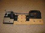
The original foot controller I made has fallen a bit into disrepair. One of the USB connections broke, and even after resoldering it, the logical sensors were behaving erratically.
So I decided it’s time to revamp the system by completely rebuilding the electronics and adding two Gemini controllers I had lying around.

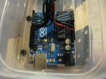
Discarding the old torn-apart point-soldered joystick I had been using, I switched to an Arduino Uno.
For those not familiar with the Arduino Uno, it has two microprocessors: the normal ATmega328 everyone has come to know and love and a somewhat slower but still fully programmable Atmega8U2 (or Atmega16U2, depending on the Uno revision). Usually the second chip just sits there, happily emulating a serial port over USB so people can reprogram the main chip easily. It is, however, capable of of much more. In fact, you can reprogram it to act as pretty much any type of USB device, including a keyboard or joystick. (It also has over a dozen wasted IO pins, many of which are unsoldered and therefore completely inaccessible, but I digress.)
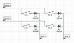
To start, I reworked the way I was reading the buttons. Instead of reading each buttons separately, which required more IO pins than the Arduino has, I opted for a scanline-based approach:

This is a 2×2 matrix, but it can be scaled as needed. For my project I used a 5×5 matrix. This allows me to use 5×5 = 25 buttons, though in this project only 22 are wired. (One button, the thumb trigger on the left controller, is wired but inaccessible, so only 21 buttons are usable.)
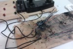
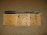
Here’s my ugly inline/dead-bug soldering of the diodes:

Here’s how it works: Set the rows to input and turn on the internal pull-up resistors (this is a chip feature). Set the groups to output and set them high. Then, to read the buttons, switch the desired group to sink instead of source and observe which rows are pulled low. (If my diodes are backwards in the diagram, forgive me.) This allows us to read the state of the buttons.
I am using “high pulled low” instead of “low pulled high” purely because the internal resistors in the Arduino are pull up, not pull down. Without the pull up resistors, the line will float and won’t always give the correct reading.
Debouncing is done in the software, namely, by having a long enough delay between each logical poll for it to not be an issue. :-/
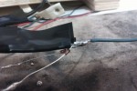
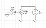
For reading the pedals, I used the standard, straightforward potentiometer reading circuit:

More on this circuit here.
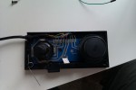
Here’s the inside of a Gemini controller:

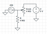
Underneath the knob is a circular resistive trace. Metal fingers brush across two “parellel” lines, making variable contact. Unlike a potentiometer, a direct proportional reading cannot easily be done. Instead, you have to use a circuit like this:

This simple voltage divider allows us to measure the position of the knob.
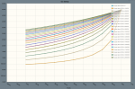
The value of the second resistor picked matters quite a bit. Here’s a graph of the voltage measured at AIN with varying resistor values. (The 1M line represents a resistor of the same value as the knob’s max):

A cool chart I made at CircuitLab, whom also generated the nice looking schematics for me.
To summarize the graph: low resistor values give you a wider sweep of the measurable range, but give very little change in the left half of rotation. I picked resistor values about the same as, or just less than, the maximum resistance of the knob. This maximizes the voltage change in the first part of the sweep, allowing me to have more accurate readings across the entire range, even if the total range is reduced.
Special note: the impedance on the Gemini dials is rather high (just under 1MΩ). To get the Arduino to read them correctly I had to follow the tips here. Basically, you have to analogRead the pin to point the Atmel’s internal mux at the pin, wait some time to let the voltage equalize, then read it again to get the real value.
Connecting everything and creating an Arduino sketch for measuring things is just regular bookwork:

More details on that can be found in the source code.
The next step was to integrate it as a multi-function USB HID device.
Working form darran’s efforts and learning how to program the USB chip, I was able to easily get the Arduino working as a joystick before doing any of the hardware work.
But, naturally, I wanted more.
After reading up a bit on the HID USB device specification and the HID usage pages, I constructed a rather ambitious HID device spec that would allow my device to act as a joystick, mouse, and keyboard all at once.
Unfortunately, as I went to upload my updated USB driver, I was greeted by this foul and unwelcome message:
dfu-programmer at90usb82 flash --debug 1 Arduino-joystick.hex
Bootloader and code overlap.
Use --suppress-bootloader-mem to ignore
Much searching the Internet yielded no good explanation as to why adding and changing a few lines of code would cause the compiled program to suddenly begin to overlap the bootloader’s memory, but through a process of trial-and-error I discovered that the error message really meant “not enough space on the chip, even though I report it as 50% free after your code.”
Not willing to collapse my enormous HID spec into something less functional, I swapped my older Arduino UNO out for my newer Arduino UNO R3 which has a newer USB chip – thereby doubling my available memory.
This led to another problem: dfu-programmer, for Linux, doesn’t support the Atmega16U2. In fairness, it doesn’t support the Atmega8U2 either, but we can work around that by telling dfu-programmer to flash a “at90usb82″ instead, which happens to function the same.
Unfortunately, the same workaround does not work for the Atmega16U2 and its counterpart “at90usb162″ because the USB device IDs aren’t the same. After searching around but finding no code to support it, I dug into the source of dfu-programmer and added support for the chip. Surprisingly, I only had to add a couple lines of code and so far it seems to work well. (The patch, “dfu-programmer-16u.diff”, can be found in the source code with everything else.)
With my patched dfu programmer and expanded memory, i was able to get the full program loaded and functioning on the USB chip.
Other notes:
- LUFA seems to have a bit of a bug with sending the keyboard report correctly, so I forced that to report to always be sent.
- Don’t leave rogue Serial.write debugging statements lying around in your code. It will cause untold headache as you try to get the binary interface between the chips working correctly.

Source code: https://bitbucket.org/sirbrialliance/foot-joy
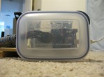
The finished project has a few small bugs I’ll fix later – in particular, the Arduino isn’t reset every time the USB device is reset and consequently the serial communication can get-out-of-sync between the two chips
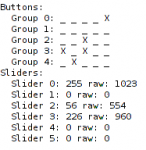
There are several modes you can use including:
- Joystick mode: Everything just maps to a slider or button as an actual joystick.
- Mouse mode: Use the sticks to move the mouse, use the pedals as a one-way ratchet to scroll up/down right/left.
- Keyboard mode: various buttons map to various keys such as the sticks which map to WASD.
- Versatile mode: A mixture, a bit of mouse, keyboard and joystick.
More details on these modes can be found in the source code. Modes are changed by pressing the mode button on the left of the right Gemini controller in conjunction with some other button.
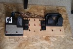
Here’s a few more photos, enjoy!
thunderzipper
by Jon on Dec.17, 2011, under Interface, Technology
I’ve been working on a protocol for communicating with many generic devices easily. Much there is that I can say about it, but it’s still fairly early prototype. I already incorporated some work from linmctool. With it, some glue, and carefully setup systems, I have been able to write a simple thunderzipper client that functions as a basic DMX light board – controlled exclusively with a PS3 controller.
It’s still quite an early prototype – and all the settings are hardcoded – but it’s still functional and a optimistic proof-of-concept of what I can do with this protocol.
I need to get work on my main “glue” application that routes everything thunderzipper.
In other news, I just pushed a commit that makes basic WiiMote buttons available and functional. (And without the need for a scan utility or setup.)
Big and Touchy
by Jon on May.29, 2009, under Interface, Technology
So I went and spent some money, (again) and got an HP TouchSmart (an IQ526 from the 22″ widescreen IQ 500 series).

Big, touchy.
Initial impressions (good):
- Made by HP, but surprisingly, didn’t have nearly as much preinstalled junk as usual.
- Looks pretty good. Aesthetically.
- The wireless mouse and keyboard work well and at a decent range.
- Once you get used to the touchscreen responding to the center (I’m used to center of pressure, like my tablet laptop), hitting the “small” buttons on the normal programs (FireFox, Windows, etc.) isn’t very difficult (especially compared to my tablet with its tiny screen but high resolution).
- It’s a big 22″ screen/computer/all-in-one that you can freakin’ touch for a few hundred dollars more than a regular touchscreen of the same size. (This price comparison was my primary purchasing reason.)
- Though nothing that comes with the computer supports it directly, and HP is shy on releasing the “drivers,” the touch hardware supports two-point multitouch.
- The included remote works well, and you can use it to navigate up/down/left/right even outside “TV” (read: Media Center) applications.
- The internal speakers are much better than I expected. They aren’t tin cans and don’t sound like tin cans.
And bad:
- The touchscreen, an IR sensor made by NextWindow, will detect a “press” even a couple millimeters from the glass.
- The “HP TouchSmat” application it comes with, supposedly the “primary” touch application you will use is crap. Slow, clunky, and it doesn’t support any multitouch when they easily could have (see below).
- No VESA wall-mounting holes. The larger (screened) model, the IQ800 series, has an adapter bracket you can buy from HP. If you want to wall-mount this model (IQ500), you either need to DIY something or get this compatible wall mount for it.
- The screen beeps when you touch it. You can turn it off in the control panel, but the beep comes back as soon as you sleep/resume. (This can be fixed, see below.)
- Not the cheapest computer around, but a well-integrated one.
- For some random reason (probably crap software I haven’t removed yet…) my F3 keypresses get intercepted and instead the volume jumps up and down and mutes like a ghost is around.

For the most part, I’m pretty impressed with it. Right now it’s just sitting next to my main computer until I can get it to a more permanent home in or near kitchenspace.
Some information on the touch screen I found after much searching:
- The touchscreen is made by NextWindow and almost fully supports two-finger multi-touch.
- You can tweak the options and remove the annoy beep permanently by downloading their Touch+ software suite. The TouchSmart has a USB (not Serial) interface. When the config screen pops up and says “USB Device not connected” just wait a second. It will detect it then give you the options. Change the sound “time” to zero and save it the the device’s permanent memory.
- If you are into Windows 7 (which apparently supports multitouch), the drivers for it are here.
- It also has an API that programmers can use to get to the multiple touches with. I haven’t found anything that will bridge this input with TUIO, the protocol used in most of today’s multi-touch software, yet. (Well, I did find one that might work from a commercial manufacturer, but I’m not looking to spend money on this point because:) I will probably just build my own bridge myself later.
[Edit: I found a program that does this. Here’s what you want to do:- Download that (TouchsmartTUIO).
- Google around or go some where to download TUIO-enabled (multi-touch) programs.
- Start TouchsmartTUIO
- (Optional, but needed for some TUIO applications) Go to Pen and Input Devices in your Control Panel and, under touch, uncheck “User your finger as an input device.” This will prevent certain applications from interpreting mouse clicks and finger touches on the smae point as two different touches.
- For flash-based TUIO apps that have a .swf instead of a .exe extension: Go to your Flash settings and enable exceptions for the TUIO .swf files you want to use. Then get the projector (choose the “Flash Player 9 Projector content debugger”). Open the .swf with this application (usually you can double-click the .swf after you instlal the projector). Once it’s open, press ctrl-f to make it full screen (if it’s not), then . . .
- Enjoy the multi-touchiness!
]
And some more random information I found about multi-touch:
- touchlib is one of the more common multi-touch libraries out there. Out of the box it supports grabbing input from a video capture device (usually a infrared modified USB camera) and turning the images to touch points. From there the interpreted data is passed to a FlashOSC server that translates the data and relays it to a local (or remote) port that Flash applications can read from. The data is sent in TUIO format, which is an extension/subset of the Open Sound Control (a “descendant” of the MIDI protocol).
- See also reacTIVision
Whee! Big touchscreen!
I might have to build a real touchwall one of these days.
Photoshopping Faster: Using Your Feet
by Jon on Mar.08, 2009, under Interface, Technology
You know what they say: Use your head.
I got a better idea: Use your feet.
I originally built my foot interface for MIDI/gaming applications but I found another great application: image editing.
I was going about filling around some lines with colors in The GIMP, and as I was working I thought, Hey, I keep switching back and forth between the paint tool and the eraser tool pretty often. When I had to switch I either needed to skim through the giant tool pallet to find my new tool, or laboriously, lift my head and chin from my left hand so I could press the appropriate keyboard shortcut. It got old, but then I thought: Hey, I’ll just use my feet.
So I fired up my AutoHotkey editing skillz and bound a couple of buttons on my foot controller to the paint and erase tools (or rather the keyboard shortcuts for them). Viola! Instant speedup.
Now I can waste away my life painting away at pointless things much more quickly!
Also, I bound another couple buttons to undo/redo to help speed up fixing my mistakes. Now I just need to figure out how to make the tools pressure sensitive using the foot pedals . . .
Edit: I also set Page Up/Page Down to buttons. Imagine how convenient it is for me to just lean back and read something long, hands free!
Stupid Stupid…
by Jon on Mar.07, 2009, under General, Interface
So, my DDR pads, you know, the ones my friend and I built from scratch? (Todo, post pages on them.)
Yeah, they broke – again. Okay, one still works fine but the other isn’t. That makes me angry. Pissed. Unhappy.
How much is a Cobalt Flux?