Author Archive
Foot Controller V2.0 – 22 button, 6-axis josystick with keyboard and mouse modes
by admin on Jul.09, 2012, under Interface, Technology
Original articles: Foot Interface, Photoshopping faster with your feet
The original foot controller I made has fallen a bit into disrepair. One of the USB connections broke, and even after resoldering it, the logical sensors were behaving erratically.
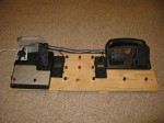
So I decided it’s time to revamp the system by completely rebuilding the electronics and adding two Gemini controllers I had lying around.

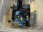
Discarding the old torn-apart point-soldered joystick I had been using, I switched to an Arduino Uno.
For those not familiar with the Arduino Uno, it has two microprocessors: the normal ATmega328 everyone has come to know and love and a somewhat slower but still fully programmable Atmega8U2 (or Atmega16U2, depending on the Uno revision). Usually the second chip just sits there, happily emulating a serial port over USB so people can reprogram the main chip easily. It is, however, capable of of much more. In fact, you can reprogram it to act as pretty much any type of USB device, including a keyboard or joystick. (It also has over a dozen wasted IO pins, many of which are unsoldered and therefore completely inaccessible, but I digress.)
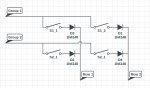
To start, I reworked the way I was reading the buttons. Instead of reading each buttons separately, which required more IO pins than the Arduino has, I opted for a scanline-based approach:

This is a 2×2 matrix, but it can be scaled as needed. For my project I used a 5×5 matrix. This allows me to use 5×5 = 25 buttons, though in this project only 22 are wired. (One button, the thumb trigger on the left controller, is wired but inaccessible, so only 21 buttons are usable.)
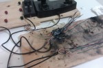
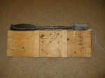
Here’s my ugly inline/dead-bug soldering of the diodes:

Here’s how it works: Set the rows to input and turn on the internal pull-up resistors (this is a chip feature). Set the groups to output and set them high. Then, to read the buttons, switch the desired group to sink instead of source and observe which rows are pulled low. (If my diodes are backwards in the diagram, forgive me.) This allows us to read the state of the buttons.
I am using “high pulled low” instead of “low pulled high” purely because the internal resistors in the Arduino are pull up, not pull down. Without the pull up resistors, the line will float and won’t always give the correct reading.
Debouncing is done in the software, namely, by having a long enough delay between each logical poll for it to not be an issue. :-/
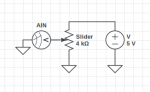
For reading the pedals, I used the standard, straightforward potentiometer reading circuit:

More on this circuit here.
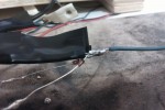
Here’s the inside of a Gemini controller:

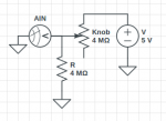
Underneath the knob is a circular resistive trace. Metal fingers brush across two “parellel” lines, making variable contact. Unlike a potentiometer, a direct proportional reading cannot easily be done. Instead, you have to use a circuit like this:

This simple voltage divider allows us to measure the position of the knob.
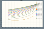
The value of the second resistor picked matters quite a bit. Here’s a graph of the voltage measured at AIN with varying resistor values. (The 1M line represents a resistor of the same value as the knob’s max):

A cool chart I made at CircuitLab, whom also generated the nice looking schematics for me.
To summarize the graph: low resistor values give you a wider sweep of the measurable range, but give very little change in the left half of rotation. I picked resistor values about the same as, or just less than, the maximum resistance of the knob. This maximizes the voltage change in the first part of the sweep, allowing me to have more accurate readings across the entire range, even if the total range is reduced.
Special note: the impedance on the Gemini dials is rather high (just under 1MΩ). To get the Arduino to read them correctly I had to follow the tips here. Basically, you have to analogRead the pin to point the Atmel’s internal mux at the pin, wait some time to let the voltage equalize, then read it again to get the real value.
Connecting everything and creating an Arduino sketch for measuring things is just regular bookwork:

More details on that can be found in the source code.
The next step was to integrate it as a multi-function USB HID device.
Working form darran’s efforts and learning how to program the USB chip, I was able to easily get the Arduino working as a joystick before doing any of the hardware work.
But, naturally, I wanted more.
After reading up a bit on the HID USB device specification and the HID usage pages, I constructed a rather ambitious HID device spec that would allow my device to act as a joystick, mouse, and keyboard all at once.
Unfortunately, as I went to upload my updated USB driver, I was greeted by this foul and unwelcome message:
dfu-programmer at90usb82 flash --debug 1 Arduino-joystick.hex
Bootloader and code overlap.
Use --suppress-bootloader-mem to ignore
Much searching the Internet yielded no good explanation as to why adding and changing a few lines of code would cause the compiled program to suddenly begin to overlap the bootloader’s memory, but through a process of trial-and-error I discovered that the error message really meant “not enough space on the chip, even though I report it as 50% free after your code.”
Not willing to collapse my enormous HID spec into something less functional, I swapped my older Arduino UNO out for my newer Arduino UNO R3 which has a newer USB chip – thereby doubling my available memory.
This led to another problem: dfu-programmer, for Linux, doesn’t support the Atmega16U2. In fairness, it doesn’t support the Atmega8U2 either, but we can work around that by telling dfu-programmer to flash a “at90usb82″ instead, which happens to function the same.
Unfortunately, the same workaround does not work for the Atmega16U2 and its counterpart “at90usb162″ because the USB device IDs aren’t the same. After searching around but finding no code to support it, I dug into the source of dfu-programmer and added support for the chip. Surprisingly, I only had to add a couple lines of code and so far it seems to work well. (The patch, “dfu-programmer-16u.diff”, can be found in the source code with everything else.)
With my patched dfu programmer and expanded memory, i was able to get the full program loaded and functioning on the USB chip.
Other notes:
- LUFA seems to have a bit of a bug with sending the keyboard report correctly, so I forced that to report to always be sent.
- Don’t leave rogue Serial.write debugging statements lying around in your code. It will cause untold headache as you try to get the binary interface between the chips working correctly.

Source code: https://bitbucket.org/sirbrialliance/foot-joy
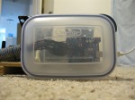
The finished project has a few small bugs I’ll fix later – in particular, the Arduino isn’t reset every time the USB device is reset and consequently the serial communication can get-out-of-sync between the two chips
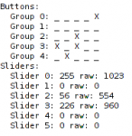
There are several modes you can use including:
- Joystick mode: Everything just maps to a slider or button as an actual joystick.
- Mouse mode: Use the sticks to move the mouse, use the pedals as a one-way ratchet to scroll up/down right/left.
- Keyboard mode: various buttons map to various keys such as the sticks which map to WASD.
- Versatile mode: A mixture, a bit of mouse, keyboard and joystick.
More details on these modes can be found in the source code. Modes are changed by pressing the mode button on the left of the right Gemini controller in conjunction with some other button.
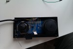
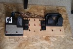
Here’s a few more photos, enjoy!